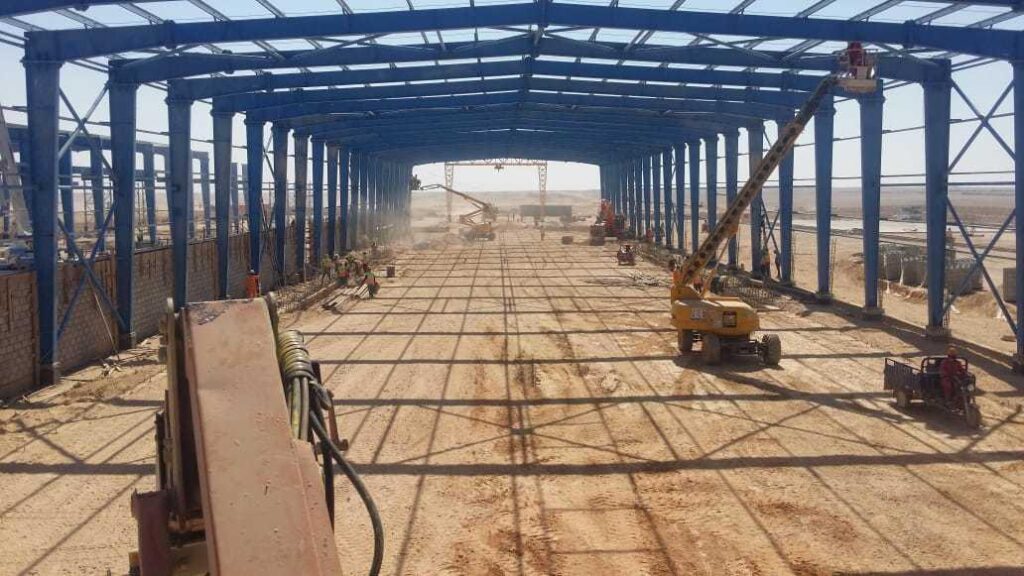
Pre-Engineered Buildings & Steel Structure Erection

1.1 Anchor Bolt Setting Plan
1.2 Roof Framing Plan
1.3 Roof Sheeting Layout
1.4 Bill of Materials (BOM)
1. Understanding the Engineering Documents
Prior to beginning the erection work, it is essential to have a clear understanding of the
Engineering Documents, especially the Erection Drawings and Bill of Materials. Erection
Drawings to be used at site should be labeled “Issued for Construction” and represent the
latest project revision. Approval Drawings should never be used at the erection site.
1.1 Anchor Bolt Setting Plan
This drawing shows the layout of all anchor bolts, it’s normally presented on one sheet, but
for relatively large buildings, this layout may be represented on two or more sheets. Erection
drawings are not made to scale, so do not attempt to scale any dimensions.
All dimensions appear in millimeters unless otherwise noted on the drawings.
The Anchor Bolt layout also includes an anchor bolt schedule, in table form, showing the,
quantities and sizes of the anchor bolts required. The key plan species out-to-out the
dimensions, bay spacing dimensions, bolt setting details and critical dimensions for the span.
Critical distance son the drawing should be respected at all times. The details specify
whether grout is required under the columns.
The grout thickness will be shown on the drawings, as well as the bolt projection. Adherence
to anchor bolt setting tolerance is important; deviation shall not exceed 6mm.
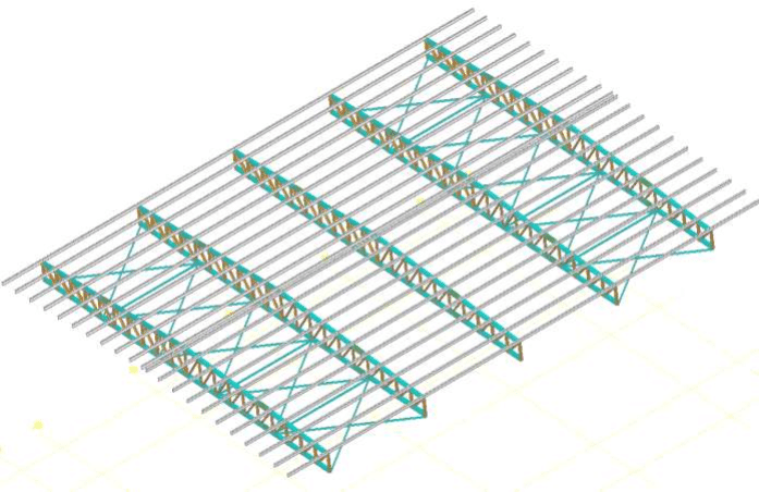
1.2 Roof Framing Plan
The roof framing plan illustrates the purlins,
Bracing and related miscellaneous details.
Part numbers are indicated on this drawing for purlins, bracing, sag rods (where applicable),
strut tubes etc. The drawings should be studied very carefully, otherwise it is possible to
overlook critical details such as nested purlins,
strut purlins, strut clips, and purlins/girts at expansion joints.
1.3 Roof Sheeting Layout
The roof sheeting plan displays all the panels including their length and part numbers. It also
shows the sky light distribution and down spout positions. Standard details of panel lap,
fasteners, trims and insulation are also included. It is very important to note the starting
dimension of the sheeting from the steel line.
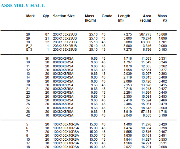
1.4 Bill of Materials (BOM)
The BOM supplied with the Erection Drawings is the Customer BOM.
The BOM begins with a cover sheet indicating the job number, building number and phase,
customer name, location, and building size.
The cover sheet also shows the number of phases in the building, any revisions, and special
notes.
The second page indicates the various sub-areas of the phases.
On the next page, the detailed BOM list of the items included in each phase begins.
The sub total of weight and the total number of items is shown at the end of each sub-area.
The last page indicates the total BOM quantity and weight.
The BOM is a reference to the items shown on the Erection Drawings and can be used to
verify that all items have been received at the site.
It is also used to identify frame weights for crane capacities.
The BOM has 9 columns indicating
1– Section size
2– Mark
3– Quantity
4– Mass (kg/m)
5– Grade
6– Length (m)
7– Area (Sq.m)
8– Mass (t)
9– Cut note


2.1 Pre-Erection Checks
2.2 Receiving Materials at Site
2. Preparation for erection
2.1 Pre-Erection Checks
Check the anchor bolt settings for compliance with the details provided on the Anchor Bolt
Setting Plan. The allowable tolerances are given in the General Notes on the drawing.
Check the foundation levels. In buildings that require grout, shim packs are placed in the
centre of the bolt pattern.
Buildings without crane systems generally do not require grout, but variances in concrete
levels may necessitate the use of shims if the concrete is outside the stated tolerances. Due to
design requirements on certain buildings, double nuts may be used.
A comprehensive survey report should be made and documented.
A site take-over report from the client will assure site accessibility and level for cranes and
trucks to maneuver freely.
The following dimensions must be controlled:
A– Steel Line to outer bolt row
B– Diagonal distance between bolt groups
C– Distance from axis center line to bolt row
C– Distance between bolts
D– Distance between frame axis
E– Distance between Steel Lines Levels of foundations Anchor Bolt protrusion Anchor bolts
in concrete foundations
2.2 Receiving Materials at Site
Receiving and unloading of materials should take place as near as possible to the place of
erection. The lay-down area should be clean and leveled.
Suitable forklift or telescopic handler is ideal for unloading, but a mobile crane is equally
suitable. In either case, care needs to be exercised in handling the various components and
bundles, to minimize damage to paint.
Protect cold-formed members such as purlins, girts, and channels from weather, by storing
the bundles with an inclination to permit water drainage in case of rain or condensation.
It is advisable to lightly cover with a tarpaulin. Bundles of sheets should be stored in the
same way, keeping the bundles clear of the ground.
Check materials against the Packing List and immediately report shortage or excess material
to OSMACOM Steel representative.

3.1 Preparation of the First Bay
3. Erection of the framing
3.1Preparation of the First Bay
Step1 we install first and second successive Gables starting by edge building
Make sure that the ridge connection is torque-tightened.
Check that slings, chain and shackles are in good condition and of adequate capacity for the
weight to be lifted.
The chains or slings should be long enough to provide sufficient spread, at an angle of not
less than45 degrees. The spread of the slings is normally calculated by dividing the member
length by four, which will give the distance of the lifting point from each end.
This formula may require some minor adjustment depending on the weight.
all bracing will be fixed as shown drawing so that the structure will be safe for lateral
stability
The purlins are then placed between the beams and connected as shown on erection
drawings.

4.1 Sheeting Preparation
4.2 Sheeting the Roof
4. Sheeting and trimming
4.1 Sheeting Preparation
Before commencing with sheeting check the details on the drawings.
A starting position will be given in relation to the steel line.
Mark the starting position, and then mark out the gauge cover width of the
sheets along the concrete notch.
This will provide a check against “creep” or “bunching “of the panels.
An important point in order for the corner trims to fit as detailed.
A full length piece is used from eave to floor, with an allowance at top and
bottom for folding over.
Tools Preparation on roof
4.2 Sheeting the Roof
Prepare the roof panels by segregating them by their length shown on the roof sheeting plan.
The sequence of roofing is from eave to ridge on both slopes finishing with the ridge panel.
To commence, it is advisable to temporarily fix one run of panels across the building to walk
on.
Adjust the line of the panel for squareness to avoid “saw-toothing” at the eave line.
Screw the panel and move progressively panel by panel up to the ridge.
After completing several runs of panel, otherwise it may break when the panel is placed
over it Ensure that the panel end-laps are as per drawing details.
Make sure that the panel ribs are kept in a straight line from eave to ridge.
Use a chalk line to mark the purlin location and maintain a straight line of screws, thus
avoiding miss-drilling and possible leakage.
End-laps have additional screws as detailed on the drawing. Proceed with the next run of
insulation, step length side tabs together, before placing the next run of panels.
When both slopes of the roof panel have been fixed, the ridge panel or ridge capes laid,
connecting both slopes. If a ridge cap issued then outside foam closures are used to fill the
panel profile, if a ridge panel is used as with Type’s’ panel, it nests without foam closures.
Bead mastic Double face tapes sheeting the roof Direction of sheeting installation

5.1 Handling & Installation
Of Sheeting
5.1.1 Unloading
5.1.2 Storage
5.1.3 Handling
5.1.4 Cutting & Fixing
5.1.5 Completion & Inspection
5.1.6 Paint Repair
5. Care & handling of sheeting
It is important to use correct sized drill bits and screws for secure fastening of panels.
During fixing, the panel should be correctly aligned and temporarily clamped to ensure the
holes are drilled correctly.
Drilling of holes produces very hot metal chips (swarf), which should be brushed off the
panel.
This should be done immediately, if possible, and the work area should be swept with a soft
broom at the end of each day work.
Care should be taken in walking on roof panels.
Workers on the roof should use soft footwear.
Metal studs or heel tips will cause damage to the painted panels.
It is important to walk in the correct place on roof panels. Always step in the valley of the
panel, which is in contact with the purlin. Standing on the high corrugations may result in
deformation of the panel. For achieving a quality job, use a screw gun with a depth locator or
torque adjuster, this will ensure correct fixing of fasteners.
When drilling use a rubber or leather thimble on the drill bit to prevent the chuck of the drill
damaging the panel paint when the drill goes through the material.
5. 1 Unloading
Sheets are packed in bundles, and may be unloaded by a suitable forklift truck or crane.
Care must be taken not to “break the back” of the sheets when unloading.
If chains or cable slings are used for unloading, good protection must be provided for the
corners of the bundle.
Note: Long panels may be difficult to handle by lifting the bundle from beneath.
Step in the valleys of the panel Stand away from high corrugations Brushing metal chips
5. 2 Storage
Packs of sheets should be stored in a safe area of the site.
They should be stored clear of the ground and elevated at one end to allow for water
drainage should they become wet.
Preferably, the bundles should be loosely covered with a tarpaulin; this will afford
additional protection but allow air circulation.
5. 3 Handling
Care should be taken when handling sheets. Erectors should use clean gloves to avoid dirty marks, oil or grease stains on sheets.
When handling individual panels from the stack, each panel should be lifted clear, not dragged along, which cause scratches.
5. 4 Cutting & Fixing
Only proper tools should be used for cutting profiled sheets.
An electric nibbler should be used for cutting across the ribs, an electric shear for cutting
longitudinally, and aviation snips for small detail work. Never use a grinding desk for cutting sheets
5. 5 Completion & Inspection
On completion, the sheeted area should be inspected.
Any ferrous objects such as pop-rivets talks, bolts, nails, screws etc. left on the roofing
should be removed.
Any accidental scratches or minor damage should be touched-up with the appropriate paint.
The area should be left clean.
5. 6 Paint Repair
For minor scratches, a small brush can be used to apply touch-up paint of matching color to
the damaged area.
If damage has affected the galvanized coating, then the damaged area should be coated with
special primer followed by a special polyurethane finish coat.

5.1 Handling & Installation
Of Sheeting
5.1.1 Unloading
5.1.2 Storage
5.1.3 Handling
5.1.4 Cutting & Fixing
5.1.5 Completion & Inspection
5.1.6 Paint Repair
6. Safety precaution
For safety reasons there are precautions that need to be taken during erection.
Make daily check on all lifting equipment.
Make daily checks on all lifting slings, check for fraying and kinking.
Check that all access equipment is in good condition, including scaffolding and ladders.
Check weather conditions, strong winds
Are dangerous during erection and sheeting.
Check for overhead electric lines before moving in with a crane.
Check that all erectors have the correct personal safety equipment, hard hats, boots, safety
harness etc.
Check electric cables for hand tools, discard frayed or split cables.
Ensure that there are sufficient guy wires on site for temporary bracing.
Ensure that erection always starts at abraded bay.
Ensure that permanent bracing and flange stays are installed as work proceeds.
Ensure that high strength bolts are used where indicated.
Ensure that high strength bolts are correctly tightened.
Maintain a clean and tidy site, thus avoiding material loss or accidents.
Tie down sheeting once the bundle is opened.
Sweep roof sheeting at the end of each day work, drill swarf will corrode the panels if not
removed. When walking on the roof, step in the valley of the panels, not the ribs.
If when waking on the roof step on the purlin lines Use the correct tools for the job, wrong
tools will damage materials and produce poor quality.
Do not step on the skylights while working on the roof .

7.1 Erection Quality Plan
The safety and Quality of Erection should been ensured by engaging experienced and
qualified Engineers, Supervisors and Technicians on the job.
The Quality Control should be effective at various stages of erection starting from receipt
inspection till the final handing over.
7.2 Testing
A visual testing will be done to all welded member of the structure. This will be done in the
fabricator’s main workshop as well as in the work site
A testing agency will be allowed to conduct tests on welding if needed by the consultant.
This could include X ray and Ultra Sonic
As for Bolts, Checking of the pre-stressing force should be at least 5 % of all the bolts. It
should be carried out with a test device corresponding to the tightening device.
NB. Please note that Osmacom will hand over the steel works for the Main Contractor
(AFAQ) first, then will hand it over to the main consultant (AMAR)

8.1 Main Erection Equipment
8.2 Electrical Equipment& Tools
8.3 Measuring & Surveying Equipment
8.4 Safety Equipment
8.5. Other Equipment
8. Basic erection equipment
8.1 Main Erection Equipment
Mobile crane
Purpose-mobile crane, used lifting beams, is used for lifting building components or
assemblies.
One, two or four mobile cranes are available, with hooks or eyes, and for different load
capacities.
They are available as a chain, wire or polyester.
The sizes and types of mobile crane required shall be determinedly the weights of the
components and assemblies to be lifted.
Clamps
Clamps are used for attaching guy wires to rafters or holding components (such as sheeting)
in place prior to fixing.
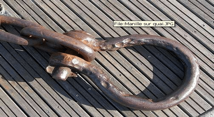
Shackles
Shackles are used for connecting slings and / or guy wires.
Note:
Shackles shall have the safe working load (S.W.L) clearly stamped
On them
Clips
Clips are used for making eyes in guy wires or for adjusting their
Lengths
Light Duty Scaffolding
Access towers are mobile work platforms, useful for sheeting walls and installing wall
accessories and trims.
Ladders
Extension ladders are used to access roofs. Mezzanines, catwalks, etc. Step ladders are free
standing ladders used for minor fixing and trimmings.
8.2 Electrical Equipment& Tools
Grinder
In pre-engineered building erection, grinders are used for cutting mild steel angles such as
base and gable angles.
Note: Sheeting shall not be cut with angle grinders. Angle grinders produce rough and
unsightly cuts, which will very quickly corrode.
Hammer Drill
Hammer drills are mainly used for the installation of expansion Bolts.
Hole Cutter
In pre-engineered buildings, all holes are pre-punched. Should circumstance dictate changes,
then the hole cutter is the ideal tool for making the required site modifications.
Pop Rivet Puller
Pop rivet pullers are used for fixing pop rivets in trims and gutter joints.
Reciprocating Saw
A reciprocating saw is ideal for cutting insulated roof and wall sandwich panels
Drill 10 mm
A 10 mm drill, with a speed of 0 to 2400 RPM (resolutions per minute), is required for predrilling holes for pop rivets and any other bolts that require field drilled holes.
8.3. Measuring & Surveying Equipment
Plumb Bob
Plumb bobs are used for plumbing vertical members up to a height of 6 m.
Measuring Tape & Square
Measuring tapes are used for miscellaneous checking, setting out and general ensuring.
A right angle square is used for setting out90* angles.
Pop Rivet Puller
Pop rivet pullers are used for fixing pop rivets in trims and gutter joints.
8.4. Safety equipment
Welding Hood
Welding hoods shall be used during welding.
Goggles
Goggles shall be used whilst cutting or grinding.
Gloves
Gloves shall be worn when handling steel components. Clean gloves should be worn while handling sheets.
Safety Harness & Fall Arrest
Safety harnesses shall be worn when working over 2 meters above the ground levels.
Safety Boots
Protective footwear shall be worn at all times while on working site to avoid toe, sole or ankle injuries.
Hard Hat
Personal head protection shall be used be on site at all times.
8.5. Other Equipment
Welding Machine
Electric welding machines are used for light duty welding such astack welding of light gauge steel members.
Oxy-acetylene Cutting Outfit
Oxy-acetylene is used for cutting steel members
